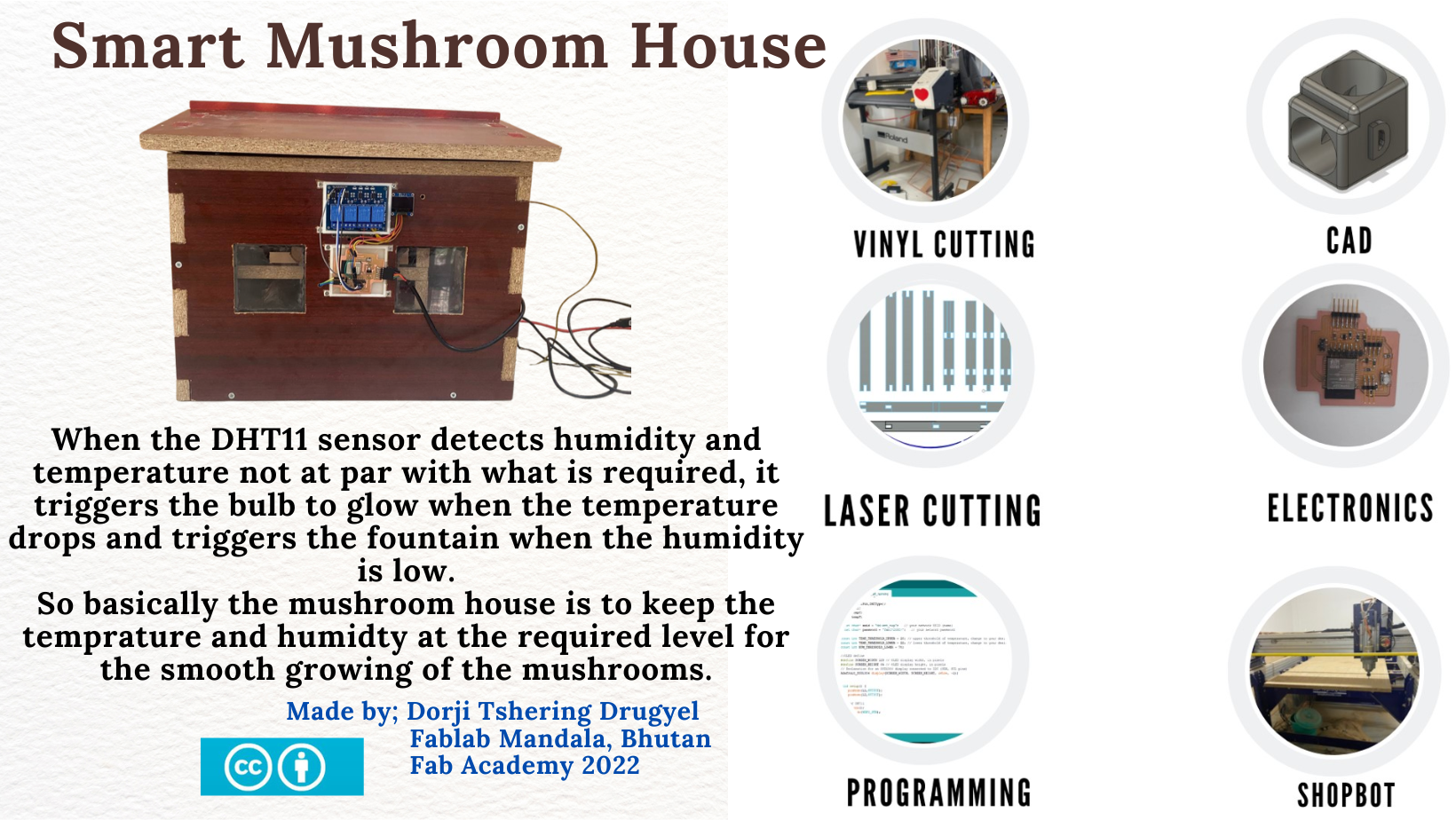
SMART MUSHROOM HOUSE
Presentation slide
Presentation video
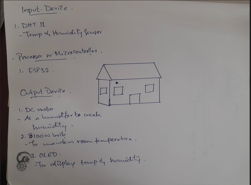
Project Idea
On first week of fab academy we were asked to select an idea and make a basic sketch for our final froject. I came up with few ideas and than discussed the idea. I decided to work on the idea to build a smart mushroom farm.
Why smart mushroom Farm
Agriculture serve as the true backbone of Bhutan's economy, contributing 33% of GDP and employing 69% of the population. Our governmernt is encouraging farmers to work on mushroom farming by giving free mushroom seeds and even supporting for building the farm. Now many farmers in Bhutan have switched to mushroom farming because mushroom farming has more advantage comparing to other farming. Mushroom famring requires less space because we can farm inside a room.
A short video clips on how bhutanese farmer grow mushroom.
There is no off season in mushroom farming but production will be less in winter comparing to summer. In summer wild mushrooms are available so the farm mushroom dont have damand on the market but in winter its off season for wild mushroom. Mushroom farming requires a lot of manual work. Everyday we have to water the bed of mushroom to mainain the moister. To maintain the moisture, famrers spray water on every log or bed where mushrooms are grown
In Bhutan, we have very cheap electricity and our government is giving free 100unit per month in rural area to encourage farmers in using electricity instead of firewood. We dont face power shortage or line disconnection, so my project idea will be effective when it is implemented.
So the main intension of my project is to reduce the manual work and make it possible to start mushroom farming in highland where mushrooms are not grown(because of low temperatures and low humidity level.)
My final project is a "Smart Mushroom house" that will automate temperature and humidity level to maintain favourable conditions for mushroom farming.
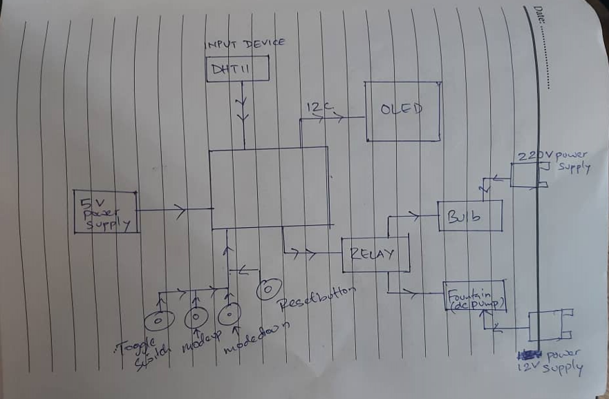
Rough sketch of my project
Objective
The main objective of my project is to design, fabricate and implement a microcontroller based prototype to monitor and control mushroom farm using sensor and output devices.
How to make it work
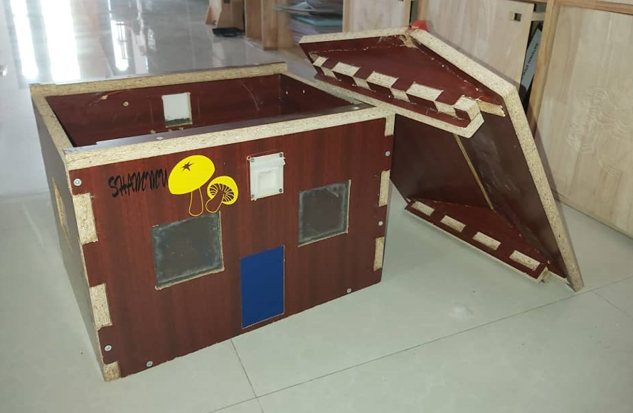
For my small-scale, automated mushroom house prototype I will design, fabricate and assemble a 60cm length, 40cm width and 40cm height enclosure to contain the 3-4 30cm long mushroom farming logs, a heater and a humidifier. The temperature and humidity automation will be controlled by an ESP32-based microcontroller (MCU) board. A DHT11 temperature & humidity sensor will be used to take measurements inside the enclosure and provide INPUT data to the ESP32.
The automation will work in the following way.
In winter the humidity will become lower than the 80% level humidity required for mushroom farming. When the sensor detects that the humidity drops below 80%, the ESP32 will activate the humidifier.
Similarly, when the sensor detects a temperature level below 25C, the ESP32 will turn on the heater.
For the humidifier system, I did research on it from google and to know how its done, I have watched a tutorial video on youtube.
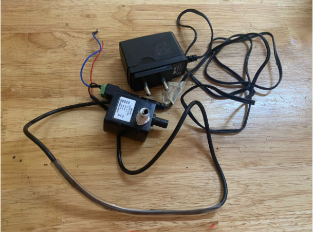
i will use a DC water pump to create a sprinkler instead of an ultrasonic humidifier
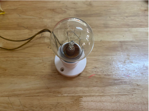
For the heater system, I will simply use heat radiated from a 100W incandescent bulb.
An OLED screen will be connected to the MCU board and display important information about the condition and status of the Smart Mushroom House prototype. During normal operation, the screen will display the current temperature and humidity levels inside the house along with the threshold level that was set to trigger the heater and humidifier ON/OFF. Additionally, Even a logo of my final project will be displayed.
On the MCU boards, I will include 3 push buttons to make it possible to adjust the temperature and humidity threshold levels up and down. One button will make it possible to toggle between ‘temperature’ and ‘humidity’ threshold adjustment modes. The other 2 buttons will be used to increase or decrease the levels up or down.
Smart Mushroom House Components
1.Enclosure:
- CNC milled plywood enclosure with plexiglass windows
2. Electronics
- ESP32 microcontroller Board (MCU)
- 1xMode Toggle Button(INPUT)
- 2x Threshold Level Adjustment Buttons(INPUT)
- 1x Reset Button (INPUT)
- 1x Programming Slide Switch (INPUT)
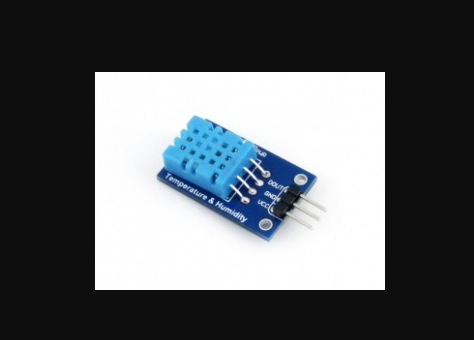
- DHT11 Temperature and humidity sensor (INPUT)
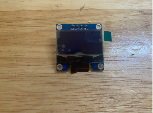
- 128px x 64px OLED display, i2c (OUTPUT)
- 2x 5V Switching Relays (OUTPUT)
- 100W Light Bulb (Heater)
- 12V DC Water Pump (Humidifier)
- Microcontroller Power Supply
- Bulb and Pump Power Supply
3. Code
- DHT11 sensor Code
- Relay Code
- Button code for Toggle and mode up/down
- OLED graphic display code
- Combination of all codes to form a Final project Code
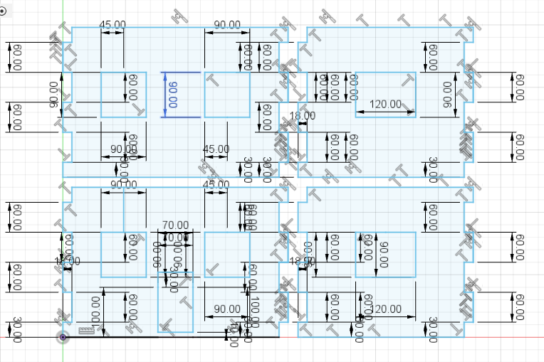
Design and Fabrication
1. 3D Design and ShopBot Milling (Subtractive)
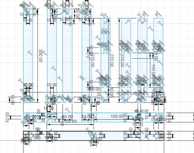
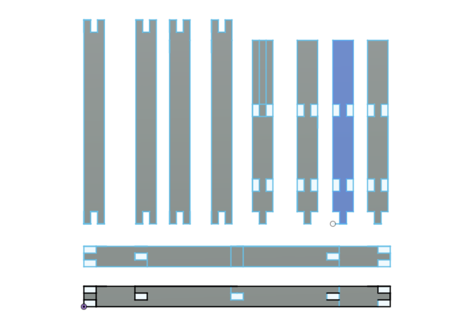
I have designed the enclosure of my project in Fision360. This is the design of four side wall

The picture below is the design of the roof of the project
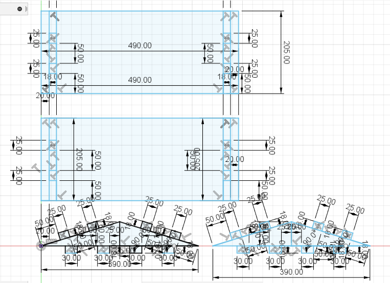
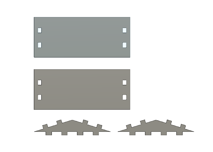
And this is the design of the pillers and other support for the Smart Mushroom House
After designing I have export the design file in DXF format and cut the design in shopbot
To export the file into DXF format, go to file and click on export
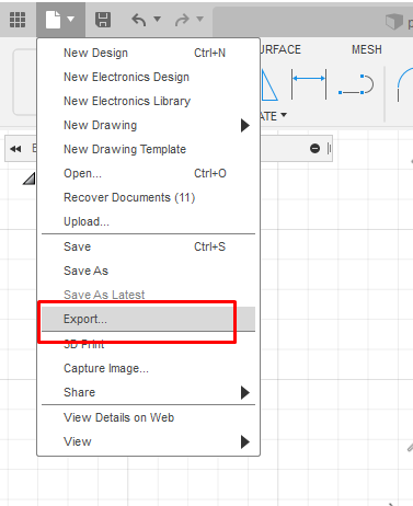
Than click on the file type we want to export. i select DXF as i wanted to cut it on ShopBot
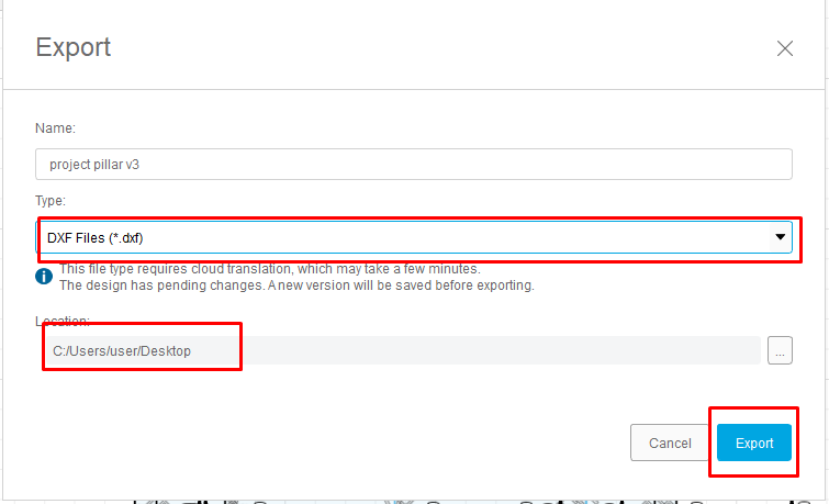
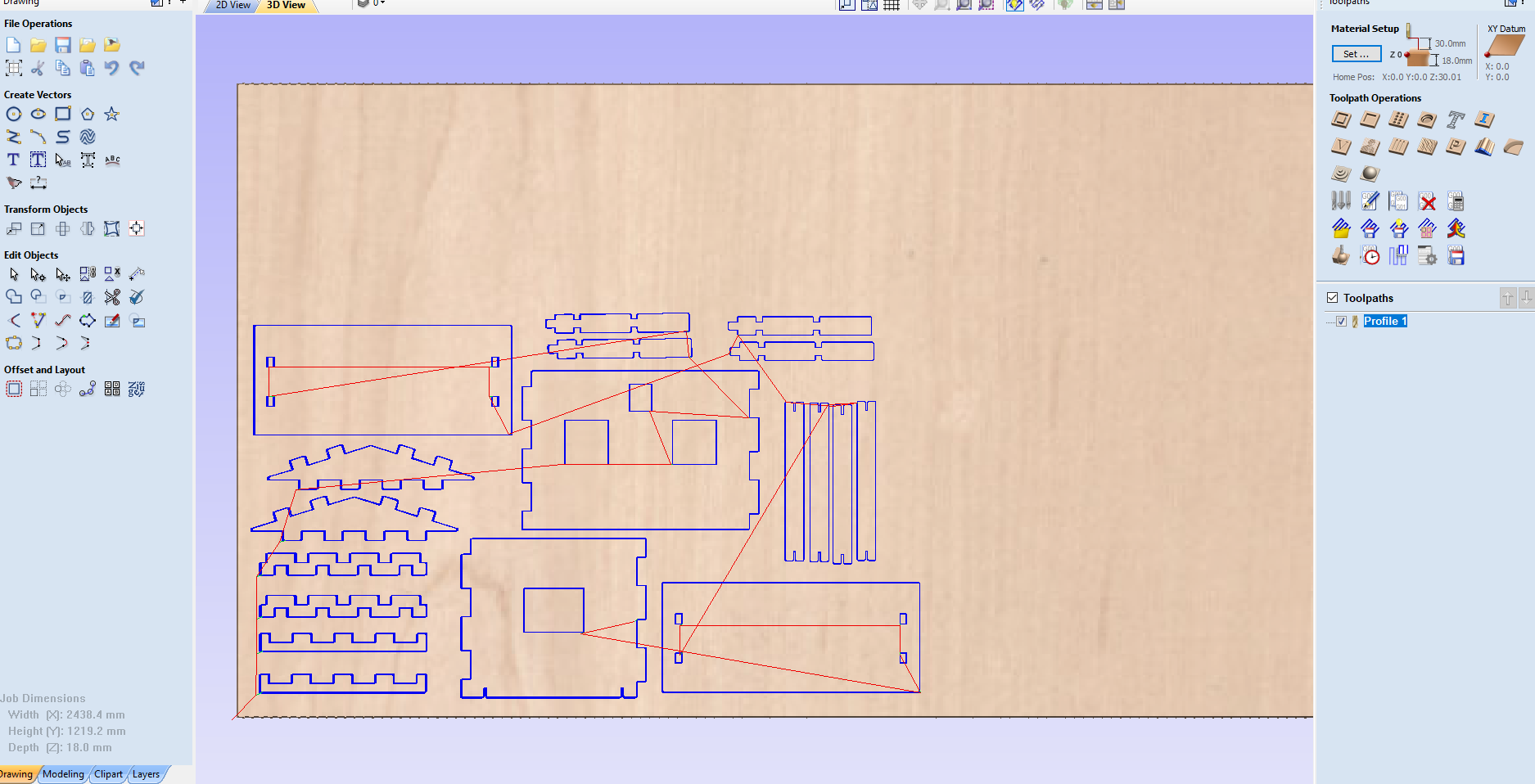
After exporting the files into DXF format I opened Aspire software. I have mentioned the steps to use Aspire on my Computer Controlled Machining week.
2. 3D Design and 3D Printing (Additive)
I have designed case for dht11, relay board, final project board, OLED and all the components required for fountain
The picture below is the design for dht11 temperature and humidity sensor case
I have even designed case for relay module as shown in picture below
Design of my final project board
Design of my oled case
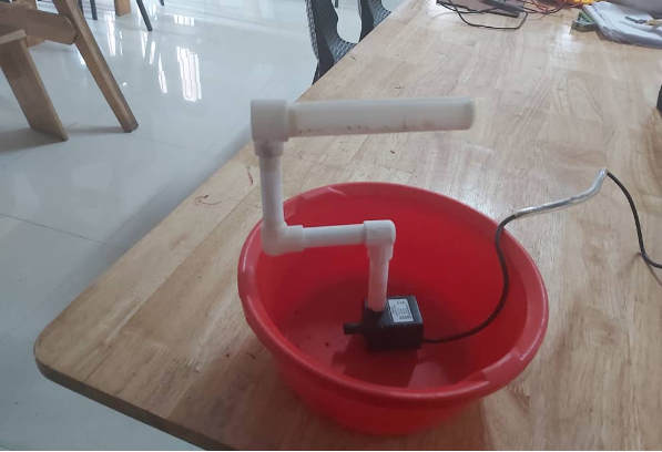
3D printed Components reqireds for humidifier 'fountain'
I have designed 3 small pipe, a water sprinkler and a connector for pipe to form a small prototype fountain.
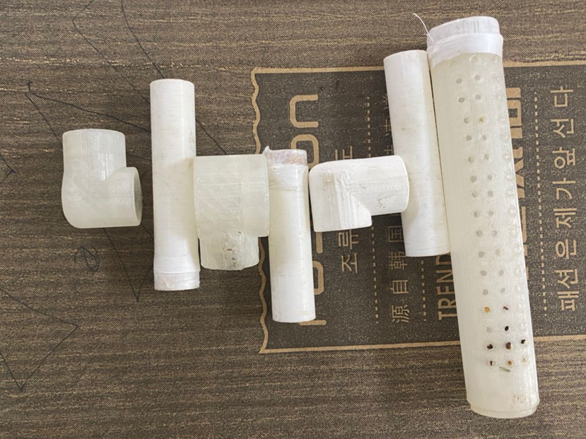
A image of assembled fountain which is printed on 3D printer
A short clips while 3D printing
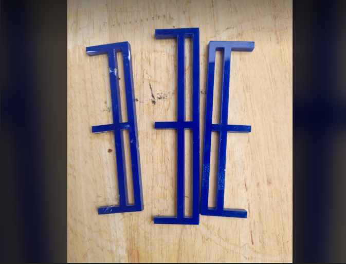
3. 2D Design and Laser cutting (Subtractive)
On laser cutter i have designed a railing to support the bowl of fountain
I have used fusion 360 to design and export the file to DXF format for laser cutting.
Steps for laser cutting i have mention in Computer Contrtolled Cutting week.
Clips of laser cutting
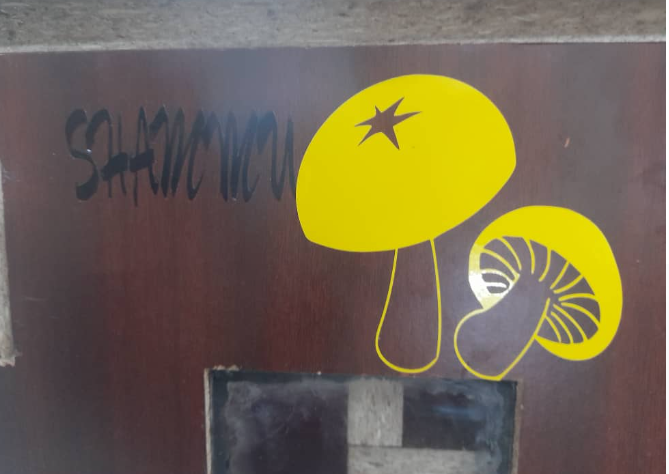
4. 2D Design and Vinyl cutting (Subtractive)
I browse for a simple image of mushroom on google to make it as a logo of my project
Than i convert the image to SVG format using online converter. Than I cut it on laser cutter
5. Electronic Design and SRM-20 Milling (Subtractive)
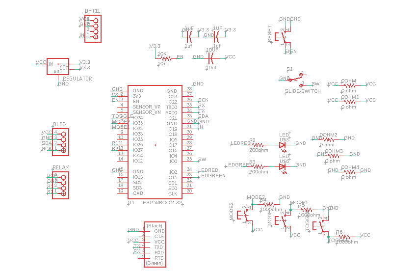
I have designed my final project board in eagle.
Schematic Design of my Final Project Board
Board Design of my Final Project Board
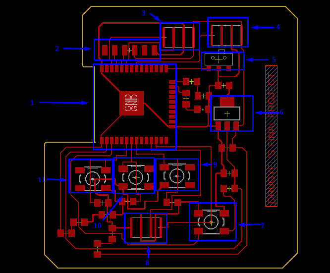
1. ESP32
2. FTDI Pin
3. I2C pin for OLED
4. DHT11 Pin(INPUT)
5. Slide Switch
6. 3.3V voltage Regulator
7. Reset Push Button
8. Relay Pin(OUTPUT)
9. Push Button for mode down
10. Push Button for mode up
11. Push Button to toggle between temperature and humidity threshold
Than i used SRM-20 to engrave the trace and cut the border
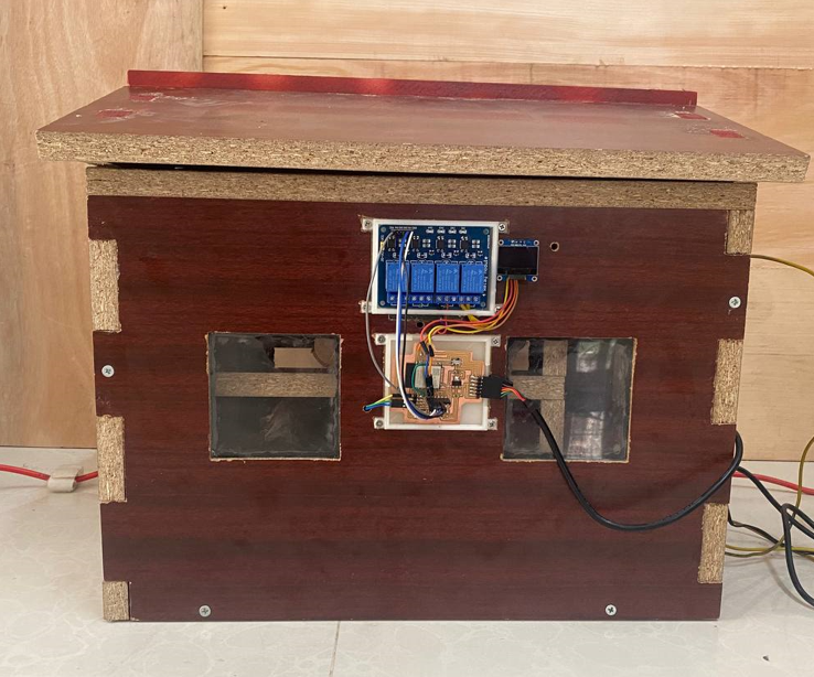
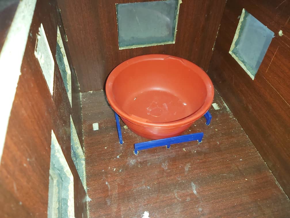
Smart Mushroom House - System Assembly
First i assemble the outer structure of the my project.The roof and wall are assembled seperately because i wanted to keep roof as a cap. Than i install pillers inside to keep the logs for growing mushroom. once the structure was ready i started to make connection for fountain and buld from relay. Connect relay with project board with jumper wair. OLED, board and relay i kept it ouside. I kept dht11 sensor in the ceter.
1. Project and Device Enclosure
microcontroller
ESP32: ESP32-WROOM is a powrful, generic Wifi + bluetooth module that targets a wide variety of applications ranging from low power sensor network to the most demanding task
Here is a link for a datasheet of ESP32-WROOM
2. Electonics
Input Device of the project
DHT11:-
Dht11 is a basic ultra low cost digital temperature and humidity sensor. It uses a humidity sensor and thermistor to measure the surrounding air and outputs a digital signal on data pin.
Buttons:-
I have used four push button on my final project board
One button is used as a reset button which is a mandatory for ESP32.
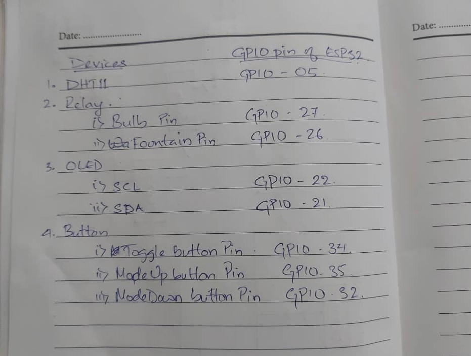
One button which is define on pin number 34 is for toggle between humidity and temperature. So that I can i uncrease or decrease the threshold value by pushing other two button.
I have define other push button on pin number 35, which will be used for increase the threshold value of temperature or humidity.
And the fourth button i have define it on pin number 32. This push button will be used to decrease the threshold value of temperature or humidity.
Output devices of my project
1. Bulb: I have built a prototype of my project so instead of heater i have used 100w bulb to maintain the temperature. When the temperature measured inside the enclosure goes below a set threshold temperature the bulb will be turned ON and when temperatur exceed the set threshold temperature it will be turned OfFF automatically
2. DC pump: I have used DC pump to make a fountain. Instead of humidifier I used dc pump to create humidity. When the humidity decrease below the set threshold humidity the fountain will be turned ON and vice versa.
3. OLED: I used OLED to diaplay the humidity and temperature inside the enclosure. The connection pin required for OLED are SDA, SCL, GND and VCC.
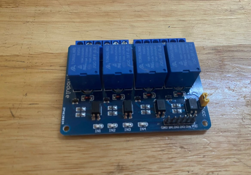
4. Relay: The relay module is an electrically operated switch which is controlled with low voltage micro controller like ESP32 to turn ON or OFF to let current flow through it.
Circuit connection
Before i start programming i did all the circuit connection.
Table of devices and ESP32's GPIO pin that is connected to
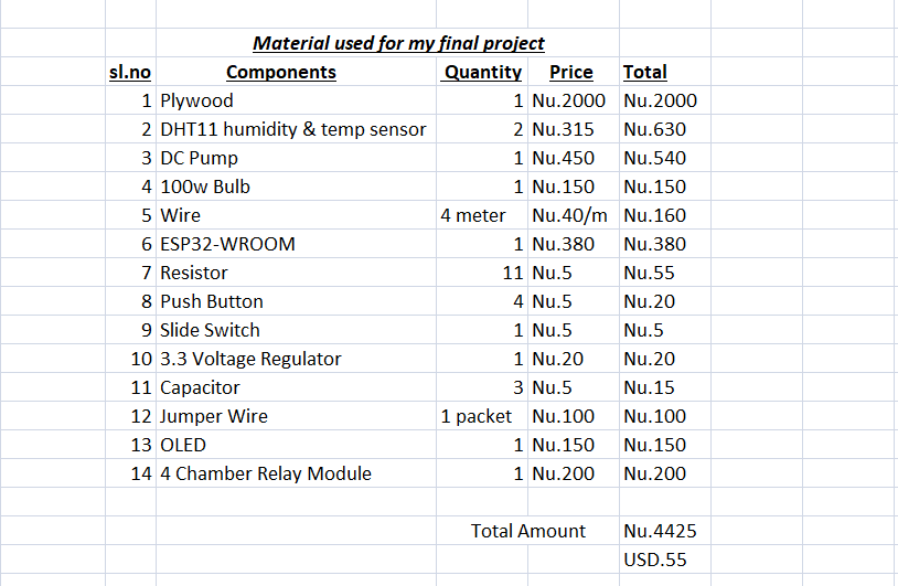
Price for the components I purchased for Final Project
3. Programming
I have divided my full final project code into four module because I wanted to test all module individually. Once the individual module uploads without error than i will combine all the code for my final project
1. DHT11 module
2. Button Module
3. OLED module
4. Realy module
1. DHT11 module
I have used DHT11 humidity and temperature sensor as a input device for my final project. The GPIO pin on ESP32 for dht11 is 5.
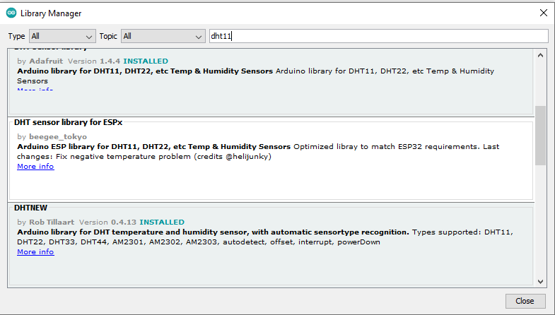
To get the code for DHT11 firstly i have to download the DHT11 library. Here is a link to download zip file of DHT11 library
After downloading I opened Arduino-IDE and installed the library. to install the library go to Sketch, than click on include library and Manage libraries as shown in image below
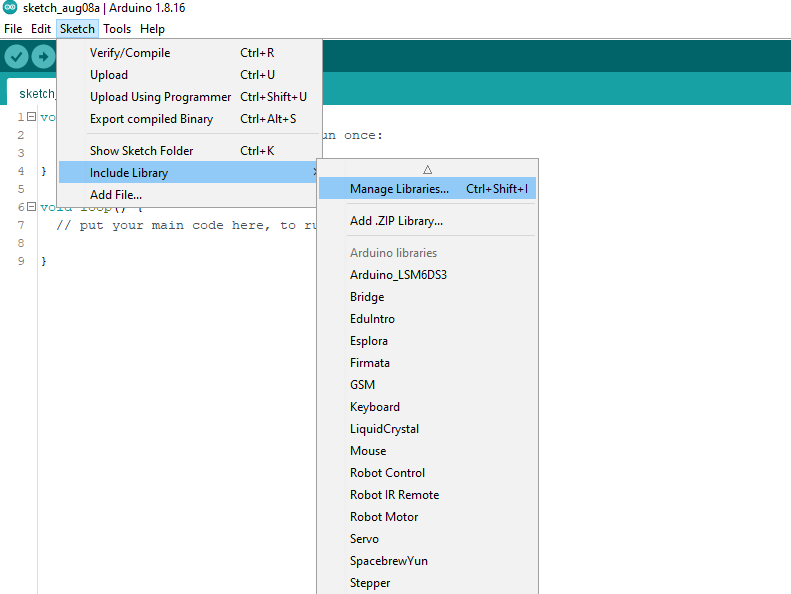
A dialog box will appear. search dht11 and install it
I surf for arduino code in google. Here is a link to get ESP32 and dht 11 code.
// Original code for OLED from Rico Kanthatham
// Modified by Dorji Tshering Drugyel
Here is a DHT11 code
					#include "DHT.h"
					#define DHT11Pin 5
					#define DHTType DHT11
					DHT HT(DHT11Pin, DHTType);
					float H;
					float T;

					#define RelayOne 26
					#define RelayTwo 27

					int humidThreshold = 80;
					int tempCThreshold = 25;

					void setup() {
					Serial.begin(9600);

					pinMode (DHT11Pin, INPUT);
					pinMode (RelayOne, OUTPUT);
					pinMode (RelayTwo, OUTPUT);


					}

					void loop() {
					  delay(2000);

					  H = HT.readHumidity();
					  T = HT.readTemperature();

					Serial.print(H);
					Serial.println("%");
					Serial.print(T);
					Serial.println("C");


					if (H < humidThreshold) {
					  digitalWrite(RelayOne, HIGH);
					} else if (H >= humidThreshold) {
					    digitalWrite(RelayOne, LOW);
					}

					if (T < tempCThreshold) {
					  digitalWrite(RelayTwo, HIGH);
					} else if (T >= tempCThreshold) {
					    digitalWrite(RelayTwo, LOW);
					}

					}
DHT11 code testing
2. Button Module
I have used 3 button for my final project. I am going to use the buttons for changing the threshold of humidity and temperature.
Toggle button
The first button is for switching between humidity threshold and themperature threshold. So that i can increase(+1) or decrease(-1) the threshold of humididity or temperature dependinding on the mode of the button.
When i press on mode button it will switch to humidity threshold and when i press again it will switch to temperature threshold.
Mode up button
This button is for increasing(+1) the value of humidity threshold or temperature threshold depending on the mode of toggle button.
I have define GPIO 35 for modeUp button
Mode Down button
This button is for decreasing (-1) the value of humidity threshold or temperature threshold by 1 depending on the mode of toggle button.
To understand better on button code i have linked below a youtube tutorial and I reffered for push button code from this tutorial and did little modification.
toggle button tutorial//modified by Dorji Tshering Drugyel, Fab Academy 2022 and Rico Kanthatham & Dronebot Workshop
//original code by Paul McWhorter
Code for push button as toggle switch, modeUp and modeDown
					int modeButtonPin = 34; //Mode Toggle Button
					int upButtonPin = 35; //value UP button
					int downButtonPin = 32; //value DOWN button

					int modeButtonNew; //current toggle button state
					int modeButtonOld = 1; //previous toggle button state...toggle button so must default to 1

					int sensorModeState = 0; //0 = Temperature, 1 = Humidity

					int tempThreshold = 25; //starting temp threshold value
					int humidThreshold = 80; //starting humid threshold value

					int debounce = 100; //wait time before reading button state...to reduce debounce issue

					void setup() {
					  Serial.begin(9600); //start serial communication at 9600 baud rate

					  //Button pins
					  pinMode(modeButtonPin, INPUT);
					  pinMode(upButtonPin, INPUT);
					  pinMode(downButtonPin, INPUT);
					}

					void loop() {

					  modeButton();
					  tempThresholdSet();
					  humidThresholdSet();

					}

					void modeButton(){

					  modeButtonNew = digitalRead(modeButtonPin);
					  delay(debounce);

					  //Toggle between Temp & Humid Threshold settings
					  if(modeButtonOld == 0 && modeButtonNew == 1) { //if button was pressed LOW and released (returns to HIGH)
					    if(sensorModeState == 0){ //...and previouos LED state was LOW or OFF
					      sensorModeState = 1; //set new LEDState to 1...or previously ON
					      //Serial.println(sensorModeState);
					    } else {
					      sensorModeState = 0;
					      //Serial.println(sensorModeState);
					    }
					  }
					  modeButtonOld = modeButtonNew;
					  //Serial.println(sensorModeState); //for debugging only...can be deleted
					}

					void tempThresholdSet(){

					  if(sensorModeState == 0 && digitalRead(upButtonPin) == HIGH) {
					    tempThreshold = tempThreshold + 1; //increase value by 1

					    Serial.print("Temperature Threshold  ");
					    Serial.print(tempThreshold);
					    Serial.print(" C");
					    Serial.println();

					    delay(30);
					  } else if (sensorModeState == 0 && digitalRead(downButtonPin) == HIGH && tempThreshold >=1) {
					    tempThreshold = tempThreshold - 1; //decrease value by 1

					    Serial.print("Temperature Threshold  ");
					    Serial.print(tempThreshold);
					    Serial.print(" C");
					    Serial.println();

					    delay(30);
					  }

					}

					void humidThresholdSet(){

					  if(sensorModeState == 1 && digitalRead(upButtonPin) == HIGH) {
					    humidThreshold = humidThreshold + 1; //increase value by 1

					    Serial.print("Humidity Threshold  ");
					    Serial.print(humidThreshold);
					    Serial.print(" %");
					    Serial.println();

					    delay(30);
					  } else if (sensorModeState == 1 && digitalRead(downButtonPin) == HIGH && humidThreshold >=1) {
					    humidThreshold = humidThreshold - 1; //decrease value by 1

					    Serial.print("Humidity Threshold  ");
					    Serial.print(humidThreshold);
					    Serial.print(" %");
					    Serial.println();

					    delay(30);
					  }

					}
Button code testing on tinkercad
Video of Successfull button code testing on my Final Project Board
The code I used basically performs the function for all three button.
3. OLED module
I used OLED to display the humidity and temperature of my Mushroom house. Even I have displayed graphic of my mushroom house logo.
For OLED I had to make 4 pin connection. That is GND, VCC, SCL and SDA.
I have included the libraries for OLED and type of OLED that I am using. That is Adafruit_SSD1306
I have linked below from where i downloaded the librarries
Link to download DHT11 library
For OLED we have to download two libraries 1. Adafruit-GFX-Library
Library of OLED type I have used Adafruit_SSD1306
To display graphics i had to generate hex code of image.
To get hex code of image follow the following steps
I have generated image code from image2cpp
Steps for generating hex code of image to display on oled
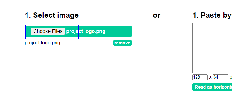
As shown on image above, I choose the file of which I wanted to generate hex code
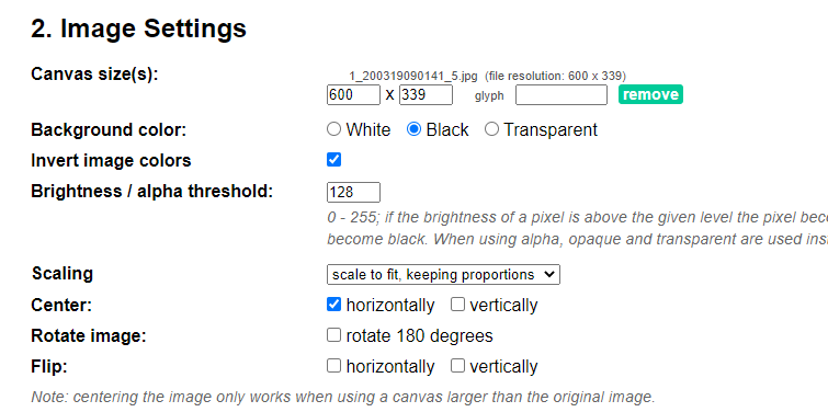
Than i define the canvas size as the size of the oled(128, 64). I kept background color as black. scaling i select scale to fit because i wanted image to fit on canvas. For center i select horizontally as the image has to be displayed on center
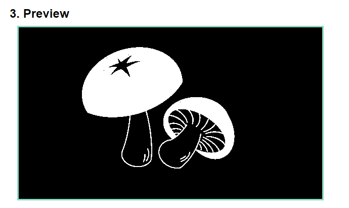
We can preview the image and adjust the tranparency of the image.
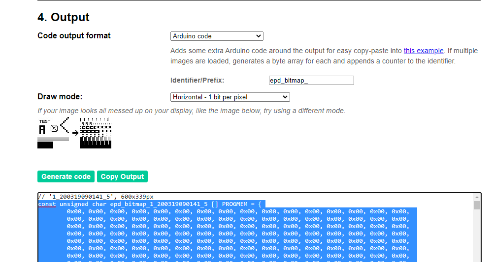
Out here i select the code output format as arduino code. Than i clicked on generate code for generating hex code to use in arduino_ide.
Copy the hex code and paste it on arduino code for oled.
OLED code for graphic display and humidity and temperature display
					#include <Wire.h> //i2c library
					#include <Adafruit_GFX.h> //adafruit graphics library
					#include <Adafruit_SSD1306.h> //adafruit SSD1306 OLED library

					#define SCREEN_WIDTH 128 // OLED display width, in pixels
					#define SCREEN_HEIGHT 64 // OLED display height, in pixels

					#define OLED_RESET     -1 // Reset pin # (or -1 if sharing Arduino reset pin)
					#define SCREEN_ADDRESS 0x3C // use the correct i2c address for your device...run i2c scanner sketch if unsure
					Adafruit_SSD1306 display(SCREEN_WIDTH, SCREEN_HEIGHT, &Wire, OLED_RESET);

					static const uint8_t  PROGMEM project_logo[] = {
					0xff, 0xff, 0xff, 0xff, 0xff, 0xff, 0xff, 0xff, 0xff, 0xff, 0xff, 0xff, 0xff, 0xff, 0xff, 0xff,
					  0xff, 0xff, 0xff, 0xff, 0xff, 0xff, 0xff, 0xff, 0xff, 0xff, 0xff, 0xff, 0xff, 0xff, 0xff, 0xff,
					  0xff, 0xff, 0xff, 0xff, 0xff, 0xff, 0xff, 0xff, 0xff, 0xff, 0xff, 0xff, 0xff, 0xff, 0xff, 0xff,
					  0xff, 0xff, 0xff, 0xff, 0xff, 0xff, 0xff, 0xff, 0xff, 0xff, 0xff, 0xff, 0xff, 0xff, 0xff, 0xff,
					  0xff, 0xff, 0xff, 0xff, 0xff, 0xff, 0xff, 0xff, 0xff, 0xff, 0xff, 0xff, 0xff, 0xff, 0xff, 0xff,
					  0xff, 0xff, 0xff, 0xff, 0xff, 0xff, 0xff, 0xff, 0xff, 0xff, 0xff, 0xff, 0xff, 0xff, 0xff, 0xff,
					  0xff, 0xff, 0xff, 0xff, 0xff, 0xff, 0xff, 0xff, 0xff, 0xff, 0xff, 0xff, 0xff, 0xff, 0xff, 0xff,
					  0xff, 0xff, 0xff, 0xff, 0xff, 0xff, 0xc0, 0x07, 0xff, 0xff, 0xff, 0xff, 0xff, 0xff, 0xff, 0xff,
					  0xff, 0xff, 0xff, 0xff, 0xff, 0xfe, 0x00, 0x01, 0xff, 0xff, 0xff, 0xff, 0xff, 0xff, 0xff, 0xff,
					  0xff, 0xff, 0xff, 0xff, 0xff, 0xf0, 0x00, 0x00, 0x3f, 0xff, 0xff, 0xff, 0xff, 0xff, 0xff, 0xff,
					  0xff, 0xff, 0xff, 0xff, 0xff, 0xc0, 0x00, 0x00, 0x1f, 0xff, 0xff, 0xff, 0xff, 0xff, 0xff, 0xff,
					  0xff, 0xff, 0xff, 0xff, 0xff, 0x80, 0x20, 0x00, 0x07, 0xff, 0xff, 0xff, 0xff, 0xff, 0xff, 0xff,
					  0xff, 0xff, 0xff, 0xff, 0xfe, 0x00, 0xe0, 0x00, 0x03, 0xff, 0xff, 0xff, 0xff, 0xff, 0xff, 0xff,
					  0xff, 0xff, 0xff, 0xff, 0xfc, 0x01, 0xfc, 0x00, 0x01, 0xff, 0xff, 0xff, 0xff, 0xff, 0xff, 0xff,
					  0xff, 0xff, 0xff, 0xff, 0xf8, 0x0f, 0xe0, 0x00, 0x01, 0xff, 0xff, 0xff, 0xff, 0xff, 0xff, 0xff,
					  0xff, 0xff, 0xff, 0xff, 0xf0, 0x03, 0xc0, 0x00, 0x00, 0xff, 0xff, 0xff, 0xff, 0xff, 0xff, 0xff,
					  0xff, 0xff, 0xff, 0xff, 0xe0, 0x06, 0x60, 0x00, 0x00, 0xff, 0xff, 0xff, 0xff, 0xff, 0xff, 0xff,
					  0xff, 0xff, 0xff, 0xff, 0xe0, 0x00, 0x20, 0x00, 0x00, 0xff, 0xff, 0xff, 0xff, 0xff, 0xff, 0xff,
					  0xff, 0xff, 0xff, 0xff, 0xc0, 0x00, 0x00, 0x00, 0x00, 0x7f, 0xff, 0xff, 0xff, 0xff, 0xff, 0xff,
					  0xff, 0xff, 0xff, 0xff, 0x80, 0x00, 0x00, 0x00, 0x00, 0x7f, 0xff, 0xff, 0xff, 0xff, 0xff, 0xff,
					  0xff, 0xff, 0xff, 0xff, 0x80, 0x00, 0x00, 0x00, 0x00, 0x7f, 0xff, 0xff, 0xff, 0xff, 0xff, 0xff,
					  0xff, 0xff, 0xff, 0xff, 0x80, 0x00, 0x00, 0x00, 0x00, 0x7f, 0xff, 0xff, 0xff, 0xff, 0xff, 0xff,
					  0xff, 0xff, 0xff, 0xff, 0x00, 0x00, 0x00, 0x00, 0x00, 0xff, 0xff, 0xff, 0xff, 0xff, 0xff, 0xff,
					  0xff, 0xff, 0xff, 0xff, 0x00, 0x00, 0x00, 0x00, 0x00, 0xff, 0xff, 0xff, 0xff, 0xff, 0xff, 0xff,
					  0xff, 0xff, 0xff, 0xff, 0x00, 0x00, 0x00, 0x00, 0x01, 0xff, 0xff, 0xff, 0xff, 0xff, 0xff, 0xff,
					  0xff, 0xff, 0xff, 0xff, 0x00, 0x00, 0x00, 0x00, 0x03, 0xff, 0xff, 0xff, 0xff, 0xff, 0xff, 0xff,
					  0xff, 0xff, 0xff, 0xff, 0x00, 0x00, 0x00, 0x00, 0x07, 0xff, 0xff, 0xff, 0xff, 0xff, 0xff, 0xff,
					  0xff, 0xff, 0xff, 0xff, 0x00, 0x00, 0x00, 0x00, 0x0f, 0xff, 0xff, 0xff, 0xff, 0xff, 0xff, 0xff,
					  0xff, 0xff, 0xff, 0xff, 0x00, 0x00, 0x00, 0x00, 0x1f, 0x80, 0x07, 0xff, 0xff, 0xff, 0xff, 0xff,
					  0xff, 0xff, 0xff, 0xff, 0x00, 0x00, 0x00, 0x00, 0x7e, 0x00, 0x01, 0xff, 0xff, 0xff, 0xff, 0xff,
					  0xff, 0xff, 0xff, 0xff, 0x00, 0x00, 0x00, 0x00, 0xf8, 0x00, 0x00, 0x7f, 0xff, 0xff, 0xff, 0xff,
					  0xff, 0xff, 0xff, 0xff, 0x80, 0x00, 0x00, 0x03, 0xf0, 0x00, 0x00, 0x3f, 0xff, 0xff, 0xff, 0xff,
					  0xff, 0xff, 0xff, 0xff, 0x80, 0x00, 0x00, 0x0f, 0xe0, 0x00, 0x00, 0x3f, 0xff, 0xff, 0xff, 0xff,
					  0xff, 0xff, 0xff, 0xff, 0xc0, 0x00, 0x00, 0x1f, 0xc6, 0xf4, 0x00, 0x1f, 0xff, 0xff, 0xff, 0xff,
					  0xff, 0xff, 0xff, 0xff, 0xe0, 0x00, 0x03, 0xdf, 0xcf, 0xff, 0x00, 0x0f, 0xff, 0xff, 0xff, 0xff,
					  0xff, 0xff, 0xff, 0xff, 0xff, 0x00, 0x6f, 0xff, 0xcf, 0xff, 0xc0, 0x0f, 0xff, 0xff, 0xff, 0xff,
					  0xff, 0xff, 0xff, 0xff, 0xff, 0xff, 0xff, 0xff, 0x9e, 0xdf, 0xf0, 0x07, 0xff, 0xff, 0xff, 0xff,
					  0xff, 0xff, 0xff, 0xff, 0xff, 0xff, 0xff, 0xff, 0x9f, 0xff, 0x68, 0x07, 0xff, 0xff, 0xff, 0xff,
					  0xff, 0xff, 0xff, 0xff, 0xff, 0xff, 0xff, 0xff, 0x8f, 0xfe, 0xfc, 0x03, 0xff, 0xff, 0xff, 0xff,
					  0xff, 0xff, 0xff, 0xff, 0xff, 0xff, 0xff, 0xff, 0x8f, 0x5f, 0xfe, 0x03, 0xff, 0xff, 0xff, 0xff,
					  0xff, 0xff, 0xff, 0xff, 0xff, 0xff, 0xff, 0xef, 0xc0, 0xbf, 0xf7, 0x03, 0xff, 0xff, 0xff, 0xff,
					  0xff, 0xff, 0xff, 0xff, 0xff, 0xff, 0xff, 0xff, 0xc7, 0xff, 0xef, 0x83, 0xff, 0xff, 0xff, 0xff,
					  0xff, 0xff, 0xff, 0xff, 0xff, 0xff, 0xdf, 0xff, 0xe0, 0xff, 0xef, 0x83, 0xff, 0xff, 0xff, 0xff,
					  0xff, 0xff, 0xff, 0xff, 0xff, 0xff, 0xff, 0xff, 0xf1, 0xff, 0xff, 0xc1, 0xff, 0xff, 0xff, 0xff,
					  0xff, 0xff, 0xff, 0xff, 0xff, 0xff, 0xff, 0xff, 0xf3, 0xff, 0xdd, 0xe1, 0xff, 0xff, 0xff, 0xff,
					  0xff, 0xff, 0xff, 0xff, 0xff, 0xff, 0xff, 0xff, 0xdf, 0xff, 0x77, 0xe3, 0xff, 0xff, 0xff, 0xff,
					  0xff, 0xff, 0xff, 0xff, 0xff, 0xff, 0xff, 0xf7, 0xff, 0xfe, 0xff, 0xc3, 0xff, 0xff, 0xff, 0xff,
					  0xff, 0xff, 0xff, 0xff, 0xff, 0xff, 0xff, 0xf7, 0xff, 0xff, 0xff, 0xc3, 0xff, 0xff, 0xff, 0xff,
					  0xff, 0xff, 0xff, 0xff, 0xff, 0xff, 0xff, 0xf7, 0xff, 0xff, 0xfe, 0xc3, 0xff, 0xff, 0xff, 0xff,
					  0xff, 0xff, 0xff, 0xff, 0xff, 0xff, 0x7f, 0xfe, 0xff, 0xfc, 0xef, 0x07, 0xff, 0xff, 0xff, 0xff,
					  0xff, 0xff, 0xff, 0xff, 0xff, 0xff, 0x7f, 0xf6, 0xff, 0xfb, 0x00, 0x0f, 0xff, 0xff, 0xff, 0xff,
					  0xff, 0xff, 0xff, 0xff, 0xff, 0xff, 0xff, 0xf6, 0xff, 0xff, 0x80, 0x0f, 0xff, 0xff, 0xff, 0xff,
					  0xff, 0xff, 0xff, 0xff, 0xff, 0xff, 0x7f, 0xff, 0xff, 0xf7, 0xe0, 0x3f, 0xff, 0xff, 0xff, 0xff,
					  0xff, 0xff, 0xff, 0xff, 0xff, 0xff, 0xff, 0xff, 0x7f, 0xff, 0xff, 0xff, 0xff, 0xff, 0xff, 0xff,
					  0xff, 0xff, 0xff, 0xff, 0xff, 0xff, 0xff, 0xef, 0xbf, 0xdf, 0xff, 0xff, 0xff, 0xff, 0xff, 0xff,
					  0xff, 0xff, 0xff, 0xff, 0xff, 0xff, 0xef, 0xbf, 0xdf, 0xbf, 0xff, 0xff, 0xff, 0xff, 0xff, 0xff,
					  0xff, 0xff, 0xff, 0xff, 0xff, 0xff, 0xff, 0xff, 0xff, 0x7f, 0xff, 0xff, 0xff, 0xff, 0xff, 0xff,
					  0xff, 0xff, 0xff, 0xff, 0xff, 0xff, 0xff, 0xff, 0xff, 0xff, 0xff, 0xff, 0xff, 0xff, 0xff, 0xff,
					  0xff, 0xff, 0xff, 0xff, 0xff, 0xff, 0xff, 0xff, 0xff, 0xff, 0xff, 0xff, 0xff, 0xff, 0xff, 0xff,
					  0xff, 0xff, 0xff, 0xff, 0xff, 0xff, 0xff, 0xff, 0xff, 0xff, 0xff, 0xff, 0xff, 0xff, 0xff, 0xff,
					  0xff, 0xff, 0xff, 0xff, 0xff, 0xff, 0xff, 0xff, 0xff, 0xff, 0xff, 0xff, 0xff, 0xff, 0xff, 0xff,
					  0xff, 0xff, 0xff, 0xff, 0xff, 0xff, 0xff, 0xff, 0xff, 0xff, 0xff, 0xff, 0xff, 0xff, 0xff, 0xff,
					  0xff, 0xff, 0xff, 0xff, 0xff, 0xff, 0xff, 0xff, 0xff, 0xff, 0xff, 0xff, 0xff, 0xff, 0xff, 0xff,
					  0xff, 0xff, 0xff, 0xff, 0xff, 0xff, 0xff, 0xff, 0xff, 0xff, 0xff, 0xff, 0xff, 0xff, 0xff, 0xff
					};

					void setup() {
					  display.begin(SSD1306_SWITCHCAPVCC, SCREEN_ADDRESS); //starts OLED screen...(generates display voltage from 3.3V, i2c address)
					  display.fillScreen(0); //zero is black
					  display.display();


					}

					void loop() {
					  display.clearDisplay();
					  display.drawBitmap(0, 0, project_logo, 128, 64, 1);
					  display.display();
					  delay(3000);

					  display.clearDisplay();
					  display.setTextColor(1);
					  display.setTextSize(2);
					  display.setCursor(1, 1);
					  display.print("SHAMU");
					  display.setTextSize(2);
					  display.setCursor(1,21);
					  display.print("MUSHROOM");
					  display.setTextSize(2);
					  display.setCursor(1,42);
					  display.print("TESTING");
					  display.display();
					  delay(3000);

					display.clearDisplay();
					  display.setTextColor(1);
					  display.setTextSize(2);
					  display.setCursor(1, 1);
					  display.print("DORJI");
					  display.setTextSize(2);
					  display.setCursor(1,21);
					  display.print("TSHERING");
					  display.setTextSize(2);
					  display.setCursor(1,42);
					  display.print("DRUGYEL");
					  display.display();
					  delay(3000);

					  display.clearDisplay();
					  display.setTextColor(1);
					  display.setTextSize(2);
					  display.setCursor(1, 1);
					  display.print("FAB");
					  display.setTextSize(2);
					  display.setCursor(1,21);
					  display.print("ACADEMY");
					  display.setTextSize(2);
					  display.setCursor(1,42);
					  display.print("2022");
					  display.display();
					  delay(3000);

					}
Short video of oled display
To unnderstand better on displaying graphics on oled i have linked on youtube
4. Relay Module
I used relay module to connect my output, which is bulb to generate heat and a water sprinkler/fountain to generate humidity.
I set a threshold for both humidity and temperature to turn ON the bulb or fountain depending on reqirement of my mushroom house, which is 25C and 80% of humidity.
Here is a link to download relay module libraries.
Relay code
					#define RelayOne 26
					#define RelayTwo 27

					void setup() {
					pinMode (RelayOne, OUTPUT);
					pinMode (RelayTwo, OUTPUT);

					}

					void loop() {
					    digitalWrite(RelayOne, LOW);
					    delay(1000);
					    digitalWrite(RelayOne, HIGH);
					    delay(1000);

					    digitalWrite(RelayTwo, LOW);
					    delay(2000);
					    digitalWrite(RelayTwo, HIGH);
					    delay(2000);
					}
Testing of Relay code
I have defined GPIO 26 and GPIO 27 as relay pins on my ESP32 board. And connected Pin26 to IN1 and Pin27 to IN2 respectively.
To know whether the relay code works on my board , I created a loop where IN1 led glows for 1 second and turns off for 1 second.
And the IN2 led was looped to glow for 2 seconds and turns off for 2 seconds.
The basic test codes I used shows the working of the relay code through the blinking of IN1 led and IN2 led
The issues I faced during my final project
After soldering my final project board i checked for circuit connection with a multimeter and there was no connection problem. So I upload my code to esp32 but it could not program. There was no error while compiling the code so i thouhgt i am having problem with my board. I check again and again but I could not find the issue.
So i decided to mill my board again and soldered it again but I faced same issue. Later one of my friend told it may be FTDI module. There is no extra FTDI module in lab nor there is FTDI cable. So i went to Super FabLab to get FTDI cable. The issue was with FTDI module. I could upload the code successfully with new FTDI cable.
After combining all the codes, I uploaded the code but button mode didnt function.
To debug the issue I worked together with my Fab Guru Rico sir and gone through many you tube tutorials. I have linked some of tutorials below.
So we concluded that the DHT11 data polling, OLED delaays and many Serial.print statements made MCU not able to hear or register button press.
In simple term, the MCU was too busy listening to data comming from DHT11 and executing the Serial.print and delay command. There was not enough time to listen for button press signal.
An interrupt Service Routine or ISR is a special custom function that runs when tiggered by an event. In my case, it is a button pressed. When an ISR function runs, it temporary breaks from the loop function and run its code and return to the loop function.
Changes I made for the interrupt
I added a code "portMUX_TYPE synch= portMUX_INITIALIZER_UNLOCKED;". The code allows interrupt routine to run
Than I change 'modeButton, thersholdUp and thresholdDown' to be an Interrupt Service Routine(ISR) function and called them in set up
I used the command 'attachinterrupt' to create interrupt functions.
The command requires 3 parameters
- The GPIO pin number
- The interrupt function name and
- The interrupt activation event
1. Falling:- Pin state goes from HIGH to LOW
2. Rising:- Pin state goes from LOW to HIGH
For each interrupt function I added 'portENTER_CRITICAL(&synch);' at the begining and added 'portEXIT_CRITICAL(&synch);' at the end. It is to allow interrupt routine to run
// Original code source Andreas Spies
Modified by Dorji Tshering Drugyel and Rico
Links for interrupt tutorial
Interupt Tutorial Interupt Tutorial Interupt TutorialSuccessful Code of my Final Project
					//Shamu Farm Control Program
					//by Dorji Drugyel, Fab Academy 2022
					//refactored from code by...Rico Kanthatham, Dronebot Workshop,...

					//oled
					#include <Wire.h> //i2c library
					#include <Adafruit_GFX.h> //adafruit graphics library
					#include <Adafruit_SSD1306.h> //adafruit SSD1306 OLED library

					#define SCREEN_WIDTH 128 // OLED display width, in pixels
					#define SCREEN_HEIGHT 64 // OLED display height, in pixels

					#define OLED_RESET     -1 // Reset pin # (or -1 if sharing Arduino reset pin)
					#define SCREEN_ADDRESS 0x3C // use the correct i2c address for your device...run i2c scanner sketch if unsure
					Adafruit_SSD1306 display(SCREEN_WIDTH, SCREEN_HEIGHT, &Wire, OLED_RESET);

					static const uint8_t  PROGMEM shamu_logo[] = {
					  0xff, 0xff, 0xff, 0xff, 0xff, 0xff, 0xff, 0xff, 0xff, 0xff, 0xff, 0xff, 0xff, 0xff, 0xff, 0xff,
					  0xff, 0xff, 0xff, 0xff, 0xff, 0xff, 0xff, 0xff, 0xff, 0xff, 0xff, 0xff, 0xff, 0xff, 0xff, 0xff,
					  0xff, 0xff, 0xff, 0xff, 0xff, 0xff, 0xff, 0xff, 0xff, 0xff, 0xff, 0xff, 0xff, 0xff, 0xff, 0xff,
					  0xff, 0xff, 0xff, 0xff, 0xff, 0xff, 0xff, 0xff, 0xff, 0xff, 0xff, 0xff, 0xff, 0xff, 0xff, 0xff,
					  0xff, 0xff, 0xff, 0xff, 0xff, 0xff, 0xff, 0xff, 0xff, 0xff, 0xff, 0xff, 0xff, 0xff, 0xff, 0xff,
					  0xff, 0xff, 0xff, 0xff, 0xff, 0xff, 0xff, 0xff, 0xff, 0xff, 0xff, 0xff, 0xff, 0xff, 0xff, 0xff,
					  0xff, 0xff, 0xff, 0xff, 0xff, 0xff, 0xff, 0xff, 0xff, 0xff, 0xff, 0xff, 0xff, 0xff, 0xff, 0xff,
					  0xff, 0xff, 0xff, 0xff, 0xff, 0xff, 0xc0, 0x07, 0xff, 0xff, 0xff, 0xff, 0xff, 0xff, 0xff, 0xff,
					  0xff, 0xff, 0xff, 0xff, 0xff, 0xfe, 0x00, 0x01, 0xff, 0xff, 0xff, 0xff, 0xff, 0xff, 0xff, 0xff,
					  0xff, 0xff, 0xff, 0xff, 0xff, 0xf0, 0x00, 0x00, 0x3f, 0xff, 0xff, 0xff, 0xff, 0xff, 0xff, 0xff,
					  0xff, 0xff, 0xff, 0xff, 0xff, 0xc0, 0x00, 0x00, 0x1f, 0xff, 0xff, 0xff, 0xff, 0xff, 0xff, 0xff,
					  0xff, 0xff, 0xff, 0xff, 0xff, 0x80, 0x20, 0x00, 0x07, 0xff, 0xff, 0xff, 0xff, 0xff, 0xff, 0xff,
					  0xff, 0xff, 0xff, 0xff, 0xfe, 0x00, 0xe0, 0x00, 0x03, 0xff, 0xff, 0xff, 0xff, 0xff, 0xff, 0xff,
					  0xff, 0xff, 0xff, 0xff, 0xfc, 0x01, 0xfc, 0x00, 0x01, 0xff, 0xff, 0xff, 0xff, 0xff, 0xff, 0xff,
					  0xff, 0xff, 0xff, 0xff, 0xf8, 0x0f, 0xe0, 0x00, 0x01, 0xff, 0xff, 0xff, 0xff, 0xff, 0xff, 0xff,
					  0xff, 0xff, 0xff, 0xff, 0xf0, 0x03, 0xc0, 0x00, 0x00, 0xff, 0xff, 0xff, 0xff, 0xff, 0xff, 0xff,
					  0xff, 0xff, 0xff, 0xff, 0xe0, 0x06, 0x60, 0x00, 0x00, 0xff, 0xff, 0xff, 0xff, 0xff, 0xff, 0xff,
					  0xff, 0xff, 0xff, 0xff, 0xe0, 0x00, 0x20, 0x00, 0x00, 0xff, 0xff, 0xff, 0xff, 0xff, 0xff, 0xff,
					  0xff, 0xff, 0xff, 0xff, 0xc0, 0x00, 0x00, 0x00, 0x00, 0x7f, 0xff, 0xff, 0xff, 0xff, 0xff, 0xff,
					  0xff, 0xff, 0xff, 0xff, 0x80, 0x00, 0x00, 0x00, 0x00, 0x7f, 0xff, 0xff, 0xff, 0xff, 0xff, 0xff,
					  0xff, 0xff, 0xff, 0xff, 0x80, 0x00, 0x00, 0x00, 0x00, 0x7f, 0xff, 0xff, 0xff, 0xff, 0xff, 0xff,
					  0xff, 0xff, 0xff, 0xff, 0x80, 0x00, 0x00, 0x00, 0x00, 0x7f, 0xff, 0xff, 0xff, 0xff, 0xff, 0xff,
					  0xff, 0xff, 0xff, 0xff, 0x00, 0x00, 0x00, 0x00, 0x00, 0xff, 0xff, 0xff, 0xff, 0xff, 0xff, 0xff,
					  0xff, 0xff, 0xff, 0xff, 0x00, 0x00, 0x00, 0x00, 0x00, 0xff, 0xff, 0xff, 0xff, 0xff, 0xff, 0xff,
					  0xff, 0xff, 0xff, 0xff, 0x00, 0x00, 0x00, 0x00, 0x01, 0xff, 0xff, 0xff, 0xff, 0xff, 0xff, 0xff,
					  0xff, 0xff, 0xff, 0xff, 0x00, 0x00, 0x00, 0x00, 0x03, 0xff, 0xff, 0xff, 0xff, 0xff, 0xff, 0xff,
					  0xff, 0xff, 0xff, 0xff, 0x00, 0x00, 0x00, 0x00, 0x07, 0xff, 0xff, 0xff, 0xff, 0xff, 0xff, 0xff,
					  0xff, 0xff, 0xff, 0xff, 0x00, 0x00, 0x00, 0x00, 0x0f, 0xff, 0xff, 0xff, 0xff, 0xff, 0xff, 0xff,
					  0xff, 0xff, 0xff, 0xff, 0x00, 0x00, 0x00, 0x00, 0x1f, 0x80, 0x07, 0xff, 0xff, 0xff, 0xff, 0xff,
					  0xff, 0xff, 0xff, 0xff, 0x00, 0x00, 0x00, 0x00, 0x7e, 0x00, 0x01, 0xff, 0xff, 0xff, 0xff, 0xff,
					  0xff, 0xff, 0xff, 0xff, 0x00, 0x00, 0x00, 0x00, 0xf8, 0x00, 0x00, 0x7f, 0xff, 0xff, 0xff, 0xff,
					  0xff, 0xff, 0xff, 0xff, 0x80, 0x00, 0x00, 0x03, 0xf0, 0x00, 0x00, 0x3f, 0xff, 0xff, 0xff, 0xff,
					  0xff, 0xff, 0xff, 0xff, 0x80, 0x00, 0x00, 0x0f, 0xe0, 0x00, 0x00, 0x3f, 0xff, 0xff, 0xff, 0xff,
					  0xff, 0xff, 0xff, 0xff, 0xc0, 0x00, 0x00, 0x1f, 0xc6, 0xf4, 0x00, 0x1f, 0xff, 0xff, 0xff, 0xff,
					  0xff, 0xff, 0xff, 0xff, 0xe0, 0x00, 0x03, 0xdf, 0xcf, 0xff, 0x00, 0x0f, 0xff, 0xff, 0xff, 0xff,
					  0xff, 0xff, 0xff, 0xff, 0xff, 0x00, 0x6f, 0xff, 0xcf, 0xff, 0xc0, 0x0f, 0xff, 0xff, 0xff, 0xff,
					  0xff, 0xff, 0xff, 0xff, 0xff, 0xff, 0xff, 0xff, 0x9e, 0xdf, 0xf0, 0x07, 0xff, 0xff, 0xff, 0xff,
					  0xff, 0xff, 0xff, 0xff, 0xff, 0xff, 0xff, 0xff, 0x9f, 0xff, 0x68, 0x07, 0xff, 0xff, 0xff, 0xff,
					  0xff, 0xff, 0xff, 0xff, 0xff, 0xff, 0xff, 0xff, 0x8f, 0xfe, 0xfc, 0x03, 0xff, 0xff, 0xff, 0xff,
					  0xff, 0xff, 0xff, 0xff, 0xff, 0xff, 0xff, 0xff, 0x8f, 0x5f, 0xfe, 0x03, 0xff, 0xff, 0xff, 0xff,
					  0xff, 0xff, 0xff, 0xff, 0xff, 0xff, 0xff, 0xef, 0xc0, 0xbf, 0xf7, 0x03, 0xff, 0xff, 0xff, 0xff,
					  0xff, 0xff, 0xff, 0xff, 0xff, 0xff, 0xff, 0xff, 0xc7, 0xff, 0xef, 0x83, 0xff, 0xff, 0xff, 0xff,
					  0xff, 0xff, 0xff, 0xff, 0xff, 0xff, 0xdf, 0xff, 0xe0, 0xff, 0xef, 0x83, 0xff, 0xff, 0xff, 0xff,
					  0xff, 0xff, 0xff, 0xff, 0xff, 0xff, 0xff, 0xff, 0xf1, 0xff, 0xff, 0xc1, 0xff, 0xff, 0xff, 0xff,
					  0xff, 0xff, 0xff, 0xff, 0xff, 0xff, 0xff, 0xff, 0xf3, 0xff, 0xdd, 0xe1, 0xff, 0xff, 0xff, 0xff,
					  0xff, 0xff, 0xff, 0xff, 0xff, 0xff, 0xff, 0xff, 0xdf, 0xff, 0x77, 0xe3, 0xff, 0xff, 0xff, 0xff,
					  0xff, 0xff, 0xff, 0xff, 0xff, 0xff, 0xff, 0xf7, 0xff, 0xfe, 0xff, 0xc3, 0xff, 0xff, 0xff, 0xff,
					  0xff, 0xff, 0xff, 0xff, 0xff, 0xff, 0xff, 0xf7, 0xff, 0xff, 0xff, 0xc3, 0xff, 0xff, 0xff, 0xff,
					  0xff, 0xff, 0xff, 0xff, 0xff, 0xff, 0xff, 0xf7, 0xff, 0xff, 0xfe, 0xc3, 0xff, 0xff, 0xff, 0xff,
					  0xff, 0xff, 0xff, 0xff, 0xff, 0xff, 0x7f, 0xfe, 0xff, 0xfc, 0xef, 0x07, 0xff, 0xff, 0xff, 0xff,
					  0xff, 0xff, 0xff, 0xff, 0xff, 0xff, 0x7f, 0xf6, 0xff, 0xfb, 0x00, 0x0f, 0xff, 0xff, 0xff, 0xff,
					  0xff, 0xff, 0xff, 0xff, 0xff, 0xff, 0xff, 0xf6, 0xff, 0xff, 0x80, 0x0f, 0xff, 0xff, 0xff, 0xff,
					  0xff, 0xff, 0xff, 0xff, 0xff, 0xff, 0x7f, 0xff, 0xff, 0xf7, 0xe0, 0x3f, 0xff, 0xff, 0xff, 0xff,
					  0xff, 0xff, 0xff, 0xff, 0xff, 0xff, 0xff, 0xff, 0x7f, 0xff, 0xff, 0xff, 0xff, 0xff, 0xff, 0xff,
					  0xff, 0xff, 0xff, 0xff, 0xff, 0xff, 0xff, 0xef, 0xbf, 0xdf, 0xff, 0xff, 0xff, 0xff, 0xff, 0xff,
					  0xff, 0xff, 0xff, 0xff, 0xff, 0xff, 0xef, 0xbf, 0xdf, 0xbf, 0xff, 0xff, 0xff, 0xff, 0xff, 0xff,
					  0xff, 0xff, 0xff, 0xff, 0xff, 0xff, 0xff, 0xff, 0xff, 0x7f, 0xff, 0xff, 0xff, 0xff, 0xff, 0xff,
					  0xff, 0xff, 0xff, 0xff, 0xff, 0xff, 0xff, 0xff, 0xff, 0xff, 0xff, 0xff, 0xff, 0xff, 0xff, 0xff,
					  0xff, 0xff, 0xff, 0xff, 0xff, 0xff, 0xff, 0xff, 0xff, 0xff, 0xff, 0xff, 0xff, 0xff, 0xff, 0xff,
					  0xff, 0xff, 0xff, 0xff, 0xff, 0xff, 0xff, 0xff, 0xff, 0xff, 0xff, 0xff, 0xff, 0xff, 0xff, 0xff,
					  0xff, 0xff, 0xff, 0xff, 0xff, 0xff, 0xff, 0xff, 0xff, 0xff, 0xff, 0xff, 0xff, 0xff, 0xff, 0xff,
					  0xff, 0xff, 0xff, 0xff, 0xff, 0xff, 0xff, 0xff, 0xff, 0xff, 0xff, 0xff, 0xff, 0xff, 0xff, 0xff,
					  0xff, 0xff, 0xff, 0xff, 0xff, 0xff, 0xff, 0xff, 0xff, 0xff, 0xff, 0xff, 0xff, 0xff, 0xff, 0xff,
					  0xff, 0xff, 0xff, 0xff, 0xff, 0xff, 0xff, 0xff, 0xff, 0xff, 0xff, 0xff, 0xff, 0xff, 0xff, 0xff
					};

					//dht11
					#include "DHT.h"
					#define DHTPIN 5 //change this pin to match connection
					#define DHTTYPE DHT11
					DHT dht(DHTPIN, DHTTYPE); //DHT11 object


					//buttons

					#define modeButtonPin 34 //Mode Toggle Button
					#define upButtonPin 35 //value UP button
					#define downButtonPin 32 //value DOWN button

					volatile bool sensorModeState = 0; //0 = Temperature, 1 = Humidity

					volatile int tempThreshold = 27; //starting temp threshold value
					volatile int humidThreshold = 80; //starting humid threshold value

					//relay
					#define RelayOne 26
					#define RelayTwo 27

					portMUX_TYPE synch = portMUX_INITIALIZER_UNLOCKED; //for ESP32...allows interrupt routines to be run

					void setup() {
					  Serial.begin(9600);
					  dht.begin();
					  display.begin(SSD1306_SWITCHCAPVCC, SCREEN_ADDRESS); //starts OLED screen

					  pinMode (DHTPIN, INPUT);
					  pinMode(modeButtonPin, INPUT);
					  pinMode(upButtonPin, INPUT);
					  pinMode(downButtonPin, INPUT);
					  pinMode (RelayOne, OUTPUT);
					  pinMode (RelayTwo, OUTPUT);

					  digitalWrite(modeButtonPin, HIGH);
					  digitalWrite(upButtonPin, LOW);
					  digitalWrite(downButtonPin, LOW);
					  digitalWrite(RelayOne, LOW);
					  digitalWrite(RelayTwo, LOW);

					  shamuSplashScreen();

					  attachInterrupt(modeButtonPin, modeButton, FALLING);
					  attachInterrupt(upButtonPin, thresholdUp, RISING);
					  attachInterrupt(downButtonPin, thresholdDown, RISING);

					}

					void loop() {

					  Serial.print("sensorModeState: ");
					  Serial.println(sensorModeState);
					  displayDHT11();

					}

					void displayDHT11() {

					  //define local variables
					  float h = dht.readHumidity();
					  float t = dht.readTemperature();

					  // Check if any reads failed and exit early (to try again).
					    if (isnan(h) || isnan(t)) {
					      Serial.println(F("Failed to read from DHT sensor!"));
					      return;
					    }

					  //Serial Debugging feedback...comment out if not needed
					  Serial.print(F("Humidity: "));
					  Serial.print(h);
					  Serial.println(F("%"));
					  Serial.print(F("Temperature: "));
					  Serial.print(t);
					  Serial.println(F("°C "));
					  Serial.print("Temperature Threshold  ");
					  Serial.print(tempThreshold);
					  Serial.println(" C");
					  Serial.print("Humidity Threshold  ");
					  Serial.print(humidThreshold);
					  Serial.println(" %");

					  display.clearDisplay(); // Clear the buffer

					  display.setTextColor(WHITE);
					  display.setTextSize(1);
					  display.setCursor(0, 0); //start position for text
					  display.print("SHAMU HOUSE");
					  display.setCursor(0, 20);
					  display.print("Humid/Set: ");
					  display.print(round(h));
					  display.print(" %/ ");
					  display.print(humidThreshold);
					  display.print(" %");
					  display.setCursor(0, 30);
					  display.print("Temp/Set: ");
					  display.print(round(t));
					  display.print(" C/ ");
					  display.print(tempThreshold);
					  display.print(" C");

					  display.display();
					  delay(2000);

					  humidCheck(round(h));
					  tempCheck(round(t));
					}

					void humidCheck(int humidity) {
					  Serial.println(humidity);
					  display.setTextColor(WHITE);
					  display.setTextSize(3);
					  display.setCursor(10, 0);
					  display.print("WATER");
					  display.display();

					  if (humidity > humidThreshold) {
					    digitalWrite(RelayOne, HIGH);
					    delay(500);
					  } else if (humidity <= humidThreshold) {
					    digitalWrite(RelayOne, LOW);
					    delay(500);
					  }

					}

					void tempCheck(int temperature) {
					  Serial.println(temperature);
					  display.setTextColor(WHITE);
					  display.setTextSize(3);
					  display.setCursor(10, 30);
					  display.print("HEAT");
					  display.display();

					  if (temperature > tempThreshold) {
					    digitalWrite(RelayTwo, HIGH);
					    delay(500);
					  } else if (temperature <= tempThreshold) {
					    digitalWrite(RelayTwo, LOW);
					    delay(500);
					  }

					}

					void modeButton() {
					  portENTER_CRITICAL(&synch); //for ESP32...allows interrupt routines to be run

					  sensorModeState = !sensorModeState; //set sensorMode to opposite of what it was before

					  portEXIT_CRITICAL(&synch); //for ESP32...allows interrupt routines to be run
					}

					void thresholdUp() {
					  portENTER_CRITICAL(&synch); //for ESP32...allows interrupt routines to be run

					  //check sensorModeState, temp or humid & check if upButton pushed
					  if (sensorModeState == 0 && digitalRead(upButtonPin) == HIGH) {
					    tempThreshold = tempThreshold + 1; //increase temperature value by 1
					  } else if (sensorModeState == 1 && digitalRead(upButtonPin) == HIGH) {
					    humidThreshold = humidThreshold + 1; //increase humidity value by 1
					  }

					  portEXIT_CRITICAL(&synch); //for ESP32...allows interrupt routines to be run
					}

					void thresholdDown() {
					  portENTER_CRITICAL(&synch); //for ESP32...allows interrupt routines to be run

					  //check sensorModeState, temp or humid & check if downButton pushed & if threshold value greater than 1
					  if (sensorModeState == 0 && digitalRead(downButtonPin) == HIGH  && tempThreshold >= 1) {
					    tempThreshold = tempThreshold - 1; //decrease temperature value by 1
					  } else if (sensorModeState == 1 && digitalRead(downButtonPin) == HIGH && humidThreshold >= 1) {
					    humidThreshold = humidThreshold - 1; //decrease humidity value by 1
					  }

					  portEXIT_CRITICAL(&synch); //for ESP32...allows interrupt routines to be run
					}

					void shamuSplashScreen() {
					  display.clearDisplay();
					  display.drawBitmap(0, 0, shamu_logo, 128, 64, 1);
					  display.display();
					  delay(3000);

					  display.clearDisplay();
					  display.setTextColor(1);
					  display.setTextSize(2);
					  display.setCursor(1, 1);
					  display.print("SHAMU");
					  display.setTextSize(2);
					  display.setCursor(1, 21);
					  display.print("HOUSE");
					  display.setTextSize(2);
					  display.setCursor(1, 42);
					  display.print("STATUS");
					  display.display();
					  delay(3000);

					  display.clearDisplay();
					  display.setTextColor(1);
					  display.setTextSize(2);
					  display.setCursor(1, 1);
					  display.print("DORJI");
					  display.setTextSize(2);
					  display.setCursor(1, 21);
					  display.print("TSHERING");
					  display.setTextSize(2);
					  display.setCursor(1, 42);
					  display.print("DRUGYEL");
					  display.display();
					  delay(3000);

					  display.clearDisplay();
					  display.setTextColor(1);
					  display.setTextSize(2);
					  display.setCursor(1, 1);
					  display.print("FAB");
					  display.setTextSize(2);
					  display.setCursor(1, 21);
					  display.print("ACADEMY");
					  display.setTextSize(2);
					  display.setCursor(1, 42);
					  display.print("2022");
					  display.display();
					  delay(3000);
					}
Assembly Of all the components and making connection
First i assemble the outer structure of the my project.The roof and wall are assembled seperately because i wanted to keep roof as a cap. Than i install pillers inside to keep the logs for growing mushroom. once the structure was ready i started to make connection for fountain and bulb from relay. Connect relay with project board with jumper wair. OLED, board and relay i kept it ouside. I kept dht11 sensor in the ceter.
Testing of my final project code
Video of succesfull testing of my final project ouside enclosure. To trigger the bulb and fountain i used toggle switch button, modeUp and modeDown button to decrease and increase the humidity and temperature threshold. As its outside enclosure it was going to take lots of time to tigger by itself.
Video of my successful final project working inside enclosure. For testing inside enclosure I didnt use buttons to increase or decrease the temperature and humidity threshold.
Acknowledgement
I would like to extend my deepest and heartfelt gratitude to firstly my remote instructor Rico Sir for teaching me Arduino Coding process, for never ending positive motivation to do better everytime and for supporting and guiding me during my time of need. For sacrificing his precious time on me
Secondly, I would like to express my thanks to Suhas Labade for teaching and making me understand about electronics and coding.
Thirdly, I would like to acknowledge Masato Takemura for teaching me about 3D Design and 3D printing
Lastly i would like to acknowledge my course mate Kencho Wangdi for assisting me on coding and Tenzin Dorji for sharing his knowledge on laser cutter and ShopBot.
I would like to acknowledge the free tutorials and documentation found in google, youtube and other free online platforms which helped me through my fab academy journey.
Original Files
Board file and schematic files
Final Project Board file Final Project Schematic fileSTL files
fountain Connector1 fountain Connector2 fountain pipe1 fountain pipe2 fountain Sprinkler Board case DHT11 case OLED case Relay case